Lesson04 RGB LED
このレッスンでは、自由な色で光るRGB LEDを使って学習してみます。スターターキットに付属しているRGB LED の色を変える実験を行います。
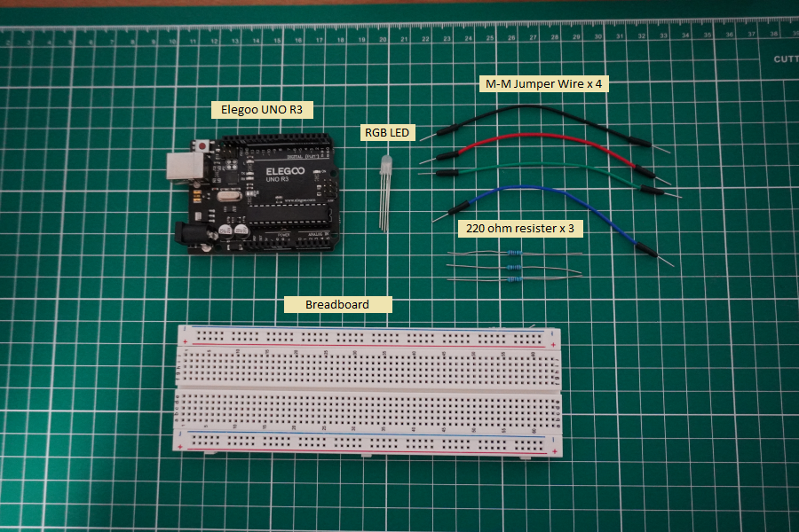
必要な部品
必要な部品は以下となります。
- Elegoo UNO R3 x 1
- Breadboard x 1
- M-M Jumper Wire x 4
- 抵抗器 x 3 (すべて220Ω)
- RGB LED x 1
リンク
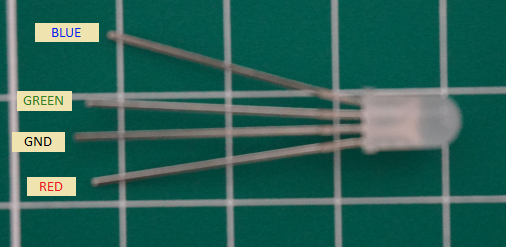
RGB LED
RGB LED は、その名の通り色の三原色であるRED(赤)、GREEN(緑)、BLUE(青)のインプットを持ちそれぞれの電流で色の強さを決めて発行する部品です。色を調整するには、レッスン03で行ったように抵抗器を変えて調整する方法がスタンダードですが、自由とは言えませんね。そこでArduino UNO R3 のPWM出力を利用します。
PWM出力
パルス幅変調(PWM)は電力を制御する技術で各LED色の輝度を制御するために使用します。このPWM出力を使うと1/500秒毎にパルスを生成します。これにより輝度を調整します。
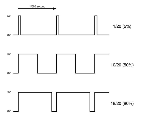
実際のArduinoのプログラムでは、パルス幅を0から255の値で指定します。
回路を作ってみる
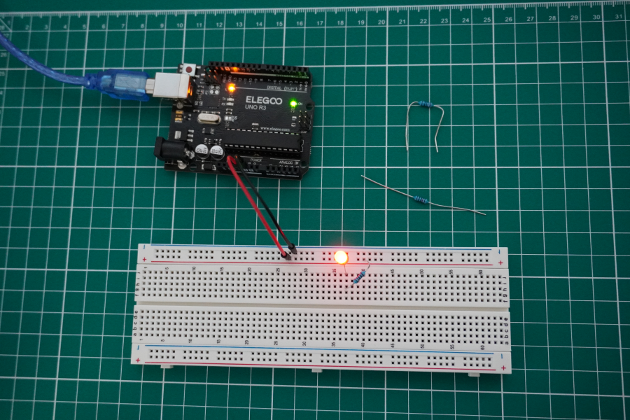
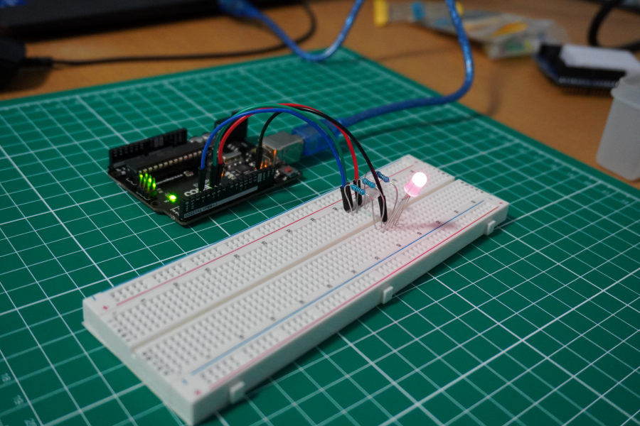
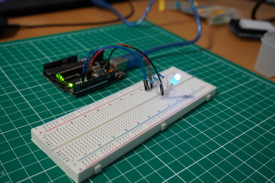
それでは、実際に回路を繋いでみます。
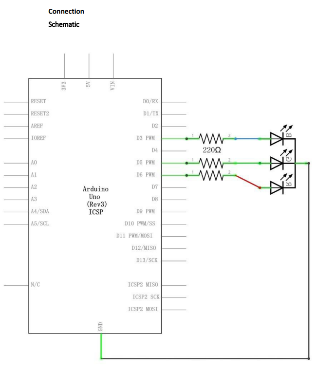
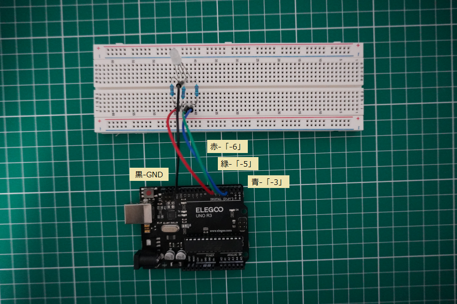
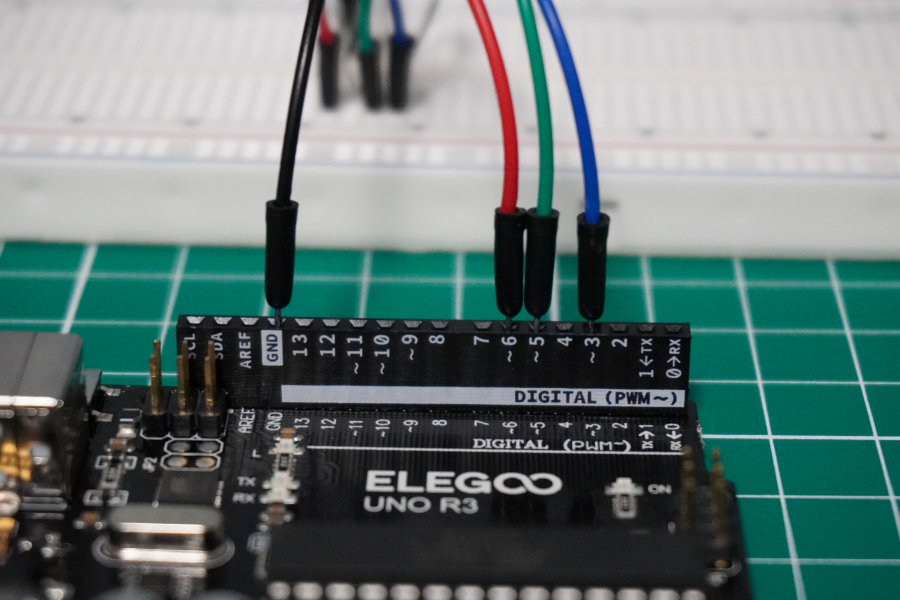
Breadboardを使って実際に繋いでみます。黒線はGNDに赤線は-6、緑線は-5、青線は-3に接続します。赤線、緑線、青線は、先に220Ωの抵抗器に接続後にRGB LEDに繋ぎます。
プログラムを動かしてみる
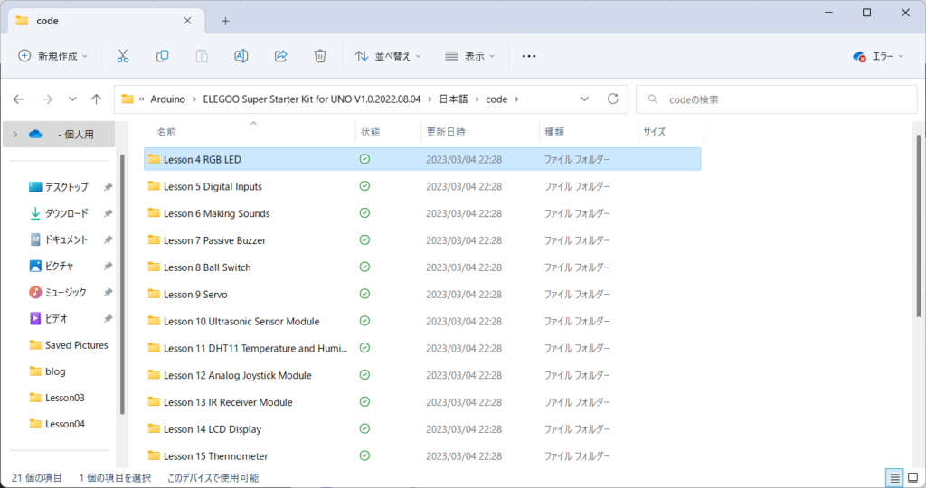
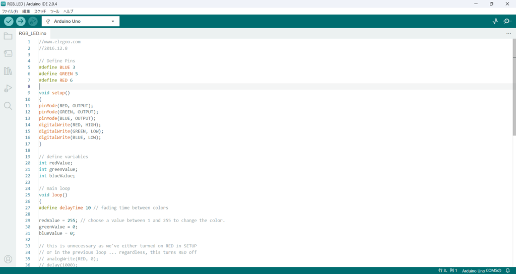
チュートリアルに付属しているコードを使って実際に動かしてみる。
//www.elegoo.com
//2016.12.8

// Define Pins
#define BLUE 3
#define GREEN 5
#define RED 6

void setup()
{
    pinMode(RED, OUTPUT);
    pinMode(GREEN, OUTPUT);
    pinMode(BLUE, OUTPUT);
    digitalWrite(RED, HIGH);
    digitalWrite(GREEN, LOW);
    digitalWrite(BLUE, LOW);
}

// define variables
int redValue;
int greenValue;
int blueValue;

// main loop
void loop()
{
    #define delayTime 10 // fading time between colors

    redValue = 255; // choose a value between 1 and 255 to change the color.
    greenValue = 0;
    blueValue = 0;

    // this is unnecessary as we've either turned on RED in SETUP
    // or in the previous loop ... regardless, this turns RED off
    // analogWrite(RED, 0);
    // delay(1000);

    for(int i = 0; i < 255; i += 1) // fades out red bring green full when i=255
    {
        redValue -= 1;
        greenValue += 1;
        // The following was reversed, counting in the wrong directions
        // analogWrite(RED, 255 - redValue);
        // analogWrite(GREEN, 255 - greenValue);
        analogWrite(RED, redValue);
        analogWrite(GREEN, greenValue);
        delay(delayTime);
    }

    redValue = 0;
    greenValue = 255;
    blueValue = 0;

    for(int i = 0; i < 255; i += 1) // fades out green bring blue full when i=255
    {
        greenValue -= 1;
        blueValue += 1;
        // The following was reversed, counting in the wrong directions
        // analogWrite(GREEN, 255 - greenValue);
        // analogWrite(BLUE, 255 - blueValue);
        analogWrite(GREEN, greenValue);
        analogWrite(BLUE, blueValue);
        delay(delayTime);
    }

    redValue = 0;
    greenValue = 0;
    blueValue = 255;

    for(int i = 0; i < 255; i += 1) // fades out blue bring red full when i=255
    {
        // The following code has been rearranged to match the other two similar sections
        blueValue -= 1;
        redValue += 1;
        // The following was reversed, counting in the wrong directions
        // analogWrite(BLUE, 255 - blueValue);
        // analogWrite(RED, 255 - redValue);
        analogWrite(BLUE, blueValue);
        analogWrite(RED, redValue);
        delay(delayTime);
    }
}
コンパイルしてアップロードしてみます。
簡単に色が変化するLEDを作れるというのはすごいですね。

コメント